|
| Place of Origin: | EU- UK |GERMANY |
| Brand Name: | FERRARI / MASERATI |
| Certification: | CE |
| Model Number: | SD3 |
| Minimum Order Quantity: | 1 Unit/Set/PCS / WhatsApp: +49 1578 9815217 |
|---|---|
| Price: | ASK FOR PRICE WhatsApp: +49 1578 9815217 |
| Packaging Details: | Brand New original factor sales package, A brand-new, unused, unopened, undamaged item in its original packaging. |
| Delivery Time: | 3-5 WORK DAYS |
| Payment Terms: | T/T BANK,PayPal with only Family & Friends, Pay with Crypto Currecy (BitCoin). |
| Supply Ability: | 10-15 Pcs /Unit/ Left in Stock |
One year free maintenance
One year free updating
Long-term technical support.
Email: germany@makobdii.com | sales@makobdii.com
Skype: MAK-OBDii_Shop
______________________________________________
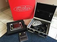
Original for FERRARI & for MASERATI Tester including the 458 and California models
For FERRARI for MASERATI SD3 Tester
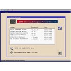
Of The SD3 Diagnostics the System IS AN Electronic Device for The Diagnostics of Electronic Control Units (the ECU) Installed in AND ECONOMICS Vehicles.
Of The SD3 Diagnostics System IS A with palmtop Device with A backlit Color the LCD the display and A membrane Keypad with Twenty Keys;
It IS Also Equipped with:
-three Standard RS232C Serial Lines;
-SiX Standard ISO9141 / CARB / 2000 KEYWORD Serial Lines;
-two Standard CAN Serial Lines Multimeter in Volts Operating Temperature Range (up to 200 V DC) and Ohm (up to 1 Mohm)
Ferrari SD2 covers all that the SD1 does (via porting software) and others such as 348, F355, 360 Modena, 456, 550, 575 and the Enzo.It works for Ferrari: Testarossa – 348 – 355 – 355 F1 – 360 Modena – 360 Spider – 360 Challenge Stradale – 456 GT – 456 M – 512tr – 550 M – 575 M – F50
CONTENTS:
MASERATI QUATTROPORTE (2004-2012) – WORKSHOP SERVICE REPAIR MANUAL FOR MASERATI
![]()
01 – Workshop Manual 2004-2012 Part One
– General information
– Engine
– Gearbox components
– Brakes
– Suspensions and wheel
– Steering system – airbag – sidebag
– Air-conditioner
– Electric-electronic system appendix
– Body work
– Toolkit
02 – Workshop Manual 2004-2012 Part Two
– Tightening torques
– Toolkit
– Removing-refitting the engine
– Circuit filling and level checks
– Right-hand side engine mount
– Elastic dowel block on the right-hand side of the engine
– Left-hand side engine mount
– Elastic dowel block on the left-hand side of the engine
– Radiators
– Oil filter
– Air filter
– Water/engine oil pump
– Tailpipe
– Catalytic converter
– Central silencer
– Exhaust extension pipe
– Electro-injectors
– Battery
– Starter motor
– Fuel tank
– Motor-driven pump pan assembly
– Anti-evaporation system
– Replacing the accelerator pedal
– Spark plugs
– Ignition coils
– Alternator
– Engine auxiliary devices' control belt
– Intake manifold
– Exhaust manifolds
– Engine removing
– Fitting and timing the engine
– Dimensional checks
– Secondary air pump
– Vacuum tank
– Pneumatic actuator control solenoid valve
– Union between pump and pipeline for air distribution to valves
– Secondary air pneumatic actuator valves
– Tightening torques
– Toolkit
– Removing-refitting the clutch
– Bleeding the clutch
– Clutch thrust bearing
– Adjusting the clutch sensor magnet
– Removing-refitting the gearbox
– Replacing the electronically-controlled gearbox control unit (tcu)
– Power unit
– Establishing the electronically-controlled gearbox oil tank level
– Kiss point (pis) ajdustment procedure
– Checking and topping-up the oil level in the gearbox housing
– Gearbox oil cooling radiator
– Clutch pressure sensor
– Deis adjustment procedure
– Accelerometer self-calibration procedure
– Acceleration sensor
– Axle shafts
– Removing-refitting the transmission shaft
– Tightening torques
– Earths location in the vehicle
– Alarm system kit replacement
– New key programming
– Component self- learning in the event of battery disconnection
– Satellite tracking system
– Sunroof control motor
– Sunroof window
– Drainage channel
– Sunroof shade
– Sunroof spoiler
– Sunroof sliding runners
– Sunroof runner alignment
– Sunroof selector switch
– Body computer node (nbc)
– Dashboard node (npl)
– Headlight set-up ecu (caf)
– Suspension control node (ncs)
– Electronically-controlled gearbox node (ncr)
– Engine control node (ncm)
– Brake system node (nfr)
– Steering angle node (nas)
– Parking sensor node (nsp)
– Power steering ecu (csg)
– Airbag node (nab)
– Luggage compartment node (nvb)
– Air conditioning and heating system node (ncl)
– Driver position node (nag)
– Driver's door node (npg)
– Passenger's door node (npp)
– Internal roof panel node (nim)
– Instrument panel node (nqs)
– Rain/twilight sensor ecu (csp)
– Windscreen wiper control unit (ctc)
– Motion-sensing alarm control unit (cav)
– Alarm system siren control unit (csa)
– Tv node (ntv)
– It info node (nit)
– Tyre pressure node ( ntp)
– Dashboard control unit (cpl)
BONUS:
03 – Aftersales Dealer Extranet
04 – Air Conditioning Software Update Campaign 144
05 – Applicable Software Listing for Engine & Transmission
06 – AWS Calibration Weight Set
07 – AWS Diagnosis and Repair Procedures
08 – Battery Diagnosis Tool
09 – Cancellation of Maserati Tech Support Emails on BOL
10 – CF Card on SD3
11 – Closing Down Campaigns
12 – Clutch Position Sensor Connector
13 – Clutch Sension Harness
14 – Digital Camera- Boroescope Kit
15 – Drive Shaft Balancing Procedure
16 – Driver Seat Harness Campaign 145
17 – Electric Parking Brake (EPB) Appendix
18 – Engine and Transmission Control Unit Reprogramming
19 – Engine Electronic Management Campaign 140
20 – Front Wheel Stone Guard Deflectors Large Stone Guards
21 – Goodwill Payments
22 – Instrument Cluster -Nack Unknown- Display
23 – Instrument Cluster Information
24 – Instrument Cluster Message – Incomplete Vehicle Data
25 – Instrument Cluster Setup
26 – Introduction of MY07 QP with Automatic Transmission and BOL~1
27 – Introduction of MY08 Grand Tusismo and BOL
28 – Kiss Point Procedure for MY06 Quattroporte
29 – M139 Quattroporte Key Programming
30 – Marketing Card Insertion and Warranty Start Date
31 – Maserati Engine and Transmission Software on Modis
32 – Maserati Scan Tool
33 – Microsoft Internet Explorer 6.0
34 – New ModisCS Warranty System Users Manual
35 – NIM Software Update Campaign 152
36 – NMA 46A Attachment A Refresh Reconditin Check
37 – NMA 46A Refresh Reconditin New Updates Information regardin~1
38 – Oil Pipe between pump and Reservoir Campaign 138
39 – Outer Door Handles (2)
40 – Outer Door Handles
41 – Parking Brake Campaign 147
42 – Passenger Air Bag Light Campaign 136 Supplemental Info
43 – Printing Software ID Labels Following Reprogramming
44 – Quattroporte Transmission Diagnosis Software
45 – Quick Release Clamp for Neg Battery Terminal
46 – RS Fule Pump Quattroporte
47 – Rear Brak Pad Noises
48 – Rear Brake Pad Replacements Requiring ABM Authorization and ~1
49 – Rear Caliper Brake Hose Campaign 139
50 – REF NO 128 Outer Door Handles RC
It can be interfaced to a PC containing the software required to update the ECU diagnostics software through one of the following lines:
>> standard RS232C serial line
>> USB serial line
>> Ethernet 10/100Mbit network
>> Ethernet Wireless 802.11b network
For better efficiency and faster data transfer between the PC and the SD3 unit, we suggest you use the USB line or an Ethernet/Wireless network for communications.
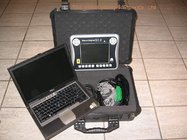
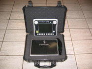
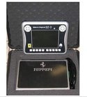
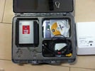
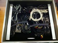
Packing List:
1. The SD3 Tester
2. Serial Cable for the SD3 / SD2 are Connection to the PC (the SD3-CBL01) [095 970 327]
3. Multimeter Cable (the SD3-CBL02) [095 970 328]
4. Power supply feeder (SD3-CBL05) [095970331]
5. EOBD SD3 diagnosis cable (SD3-CBL06) [095970332]
6. Diagnosis cable with SD2 bridle (SD3-CBL07) [095970333]
7. Connection cable for feeding Among SD2 and SD3 bridle (SD3 -CBL08) [095970334]
8. Cigar lighter socket feeder (SD3-CBL09) [095970335]
9. ISO 1 extension (SD3 -CBL10) [095970336]
10. ISO 2 extension (SD3 -CBL11) [095970337]
11. SD2 B -CAN adapter (SD3-CBL12)
12. USB cable [095970330]13. 10/100 Mbps Ethernet cross-over cable [095970329]
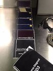
13. SD3 wireless board; SD3 Manual [095970324] with 475 Resource CD
14. SD3 Quick Reference Installation CD-ROM Software [095970326]8
15. Metal-point rods For Multimeter
16. Tablet PC USB/Wireless board
17.User's Manual and Getting Started Guide
18.Power Module and Recharger
To install the Basic SD3NET software on the PC, proceed as follows:
1. Power the the PC where the program has to be installed;
2. Insert the program CD supplied with the SD3 in the CD drive.
3. If the user has enabled The AUTORUN function on the CD drive, the installation wizard will launch automatically ; in this case go to point 7, otherwise continue the procedure below;
4. Using your mouse, double-click on MY COMPUTER;
5. When the computer resources window opens Double-click on the CD icon where the SD3NET program has been inserted ;
6. The window of The Double-A website Opens the Showing of The Clicking the Contents of the CD of The Double the ON The The The the SETUP.EXE the Installation of the Click of The Wizard Will now the RUN; ..
7. The window of The displayed for the BE A of The Will of The Language of The Selection of During Program Installing to use.
8. The installation wizard displays a start window. Click on NEXT to continue;
9. You will be prompted to install Microsoft Framework NET 1.1 (if It is not present). Always confirm and proceed with installation;
10. You are asked to name The directory in which the program will be installed (we recommend leaving the default setting). Click on NEXT to continue ;
11. You are asked to The Directory in Which the DATA name The Program Will BE Installed (WE Recommend Leaving Setting The default) Continue to the Click the NEXT ON;.
. 12. The window of The Last Gives A Summary of The Previous Selections The Press and the NEXT COPYING The Program System Soho starts to your PC.
13. When the installation has terminated you will be asked to reboot your PC. This is essential for the program to operate correctly;
14. When the PC has been rebooted, the SD3NET? icon will appear on the desktop.
![]()
Multimeter
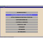
The SD3 Diagnostics System has an integrated multimeter that can take measurements in Volts (up to 200 V dc) and Ohms (up to 1 Mohm). This function can be selected from the SD3 Tester main menu.
Scantool OBD
The SD3 Diagnostics System has an integrated Standard Scantool OBD software. This system makes it possible to automatically check for systems able to support the service (engine, shift, …). Once the control unit has been identified by the software, you can Check some parameters/errors supplied by the system itself.
This function can be selected from the SD3 Tester main menu.
Power supply voltage
The SD3 requires a voltage between 8 and 16 V DC which is supplied either by the battery of the vehicle being tested or by the power supply provided with the product.
Installation instructions for the SD3
The SD3 does not require any installation; it only needs to be configured with the diagnostics software to be used. The downloaded software are stored in the non-volatile memory of the SD3 unit. The SD3 is equipped with a battery-powered clock which can Be set and checked on the PC through a special software menu.
General Description
The figures are provided a diagram of the upper part (containing the power supply and diagnostics connectors), front part of the SD3 unit (containing the display, keypad and ON light) and the lower part (containing a flap which provides access to the lower part Part Part Used to hook up an American PS2 keyboard for the PC, and two PCMCIA connectors used for any hardware expansions-eg flash expansions, Wireless card-through external boxes).
The ten keys at the bottom of the screen are used to input data (numbers/letters) into the diagnostics software.
The directional arrows and the TAB key feature function repetition if the key is held down continuously.
In all menus, hold down “Switch” and “Esc” for 4 seconds to reset the SD3 Tester software. This speeds up restarting the device if the software crashes (the Tester does not respond to the keywords commands).
The top holds the following:
· The power button.
· One 25-pin connector for power and serial diagnostics lines (on the power button side);
· One 9-pin connector (male) for hook up to the PC (in the centre);
· One 9-pin connector (female) for Multimeter inlet.
· One Ethernet 10/100 Mbit connector.
· One USB connector.
· One Connector to hook up a CRT VGA monitor
Self test
To quickly check that the device is functional, connect the power supply (for example, with the cord
And the mains power supply), press the power button and check that the led lights up. Within 20/30 seconds
The start icon appears on the display.
The SD3 has a resettable fuse. If it is activated because of an internal fault or due to the external cabling,
Wait a few minutes to allow it to reset. If, when you switch on the SD3, the display does not light up, wait a
Few minutes and repeat the procedure.
| Emerson Process Management Rosemount Field Communicator 475 Features | |
| Microprocessor | 80 MHz Hitachi SH3 |
| Memory Internal Flash | 32MB |
| System Card | 1GB Secure Digital Card |
| RMB | 32MB |
| Weight | Approx. 1.65 1b (0.75kg) with Battery |
| Display | 1/4 VGA (240 * 320 px) color, 3.5 in (8,9 cm) transreflective display with touchscreen, anti-glare coated |
| Keypad | 25 keys including 4 action keys, 12 alphanumeric keys, tab key, function key, backlight key, power key, and 4 cursor-control (arrow) keys;membrane design with tactile feedback |
| Battery | Rechargeable lithium-lon power module |
| Battery Charger | Min DIN 6-pin Jack |
| Environment Usage |
10° C (14° F) to +50° C (122° F) |
| HART Fieldbus |
Three 4mm banana plugs (one common to HART and Foundation fieldbus) |
| Blue tooth | Up to 32.8 ft (10 m) communication distance Uses standard Windows drivers FCC, IC and CE approvals |
| Easy Upgrade Requirements |
Usage
PC with Internet access
CD Rom drive
IrDA port (or adapter) or Bluetooth (or adapter)
SD Card Reader (required for some upgrades)
Windows XP (SP2 or SP3) or Windows Vista Business (SP1)
|
Each Unit Includes
Shipment Note:
If your package shipped by Express Delivery, please give us a valid delivery details like your complect name, company name, phone number, and also a full and accurate shipping address.
Contact us:
Our office hours:
Am8: 30-PM11: 00
Contact Information.
Live Support: Chat with us online
Email: germany@makobdii.com | sales@makobdii.com
Skype: MAK-OBDii_Shop